


Brass distribution manifolds - CD Series

The CD series manifolds are obtained from drawn brass bar with yellow* or nickel-plated finish.
All manifolds undergo a post weld heat treatment to eliminate any tension caused from processing. Do only use Luxor manifolds with Luxor accessories with soft o-ring sealing.
All of Luxor fittings and accessories for manifolds (such as drain valves, plugs, etc.) are provided with this kind of sealing and do not require the use of any intermediate element (PTFE, hemp, etc.), which could result in cracks. We recommend to tighten the fittings to a maximum torque of 60 Nm.
* In compliance with D.M. 174/2004


Max temperature
120 °C

Max pressure
10 bar

Materials
CW617N
UNI EN
12165:2016

Knob
ABS bianco
RAL 9016

Stem
AISI 316

Testing
100%
TECHNICAL SPECIFICATIONS WITH THERMOELECTRIC HEAD ART. TE
Working temperature range
0 °C ÷ 100 °C
Room temperature
0 °C ÷ 60 °C

Max relative humidity
80%
TECHNICAL SPECIFICATIONS WITH FLOW REGULATORS ART. TM 4012
Max temperature
70 °C
Max pressure
6 bar

Copper pipe
W 24x19 - TR 91
G 3/4 EK - TR 91/A

Plastic pipe
W 24x19 - TP 95
G 3/4 EK - TP 98

Multilayer pipe
W 24x19 - TP 97
G 3/4 EK - TP 99

MAIN BODY CONNECTION
G 3/4
G 1"
G 1"1/4

CENTRE TO CENTRE DISTANCE
| G 3/4 | 40 mm | |
| G 1" | 50 mm | |
| G 1"1/4 | 50 mm |

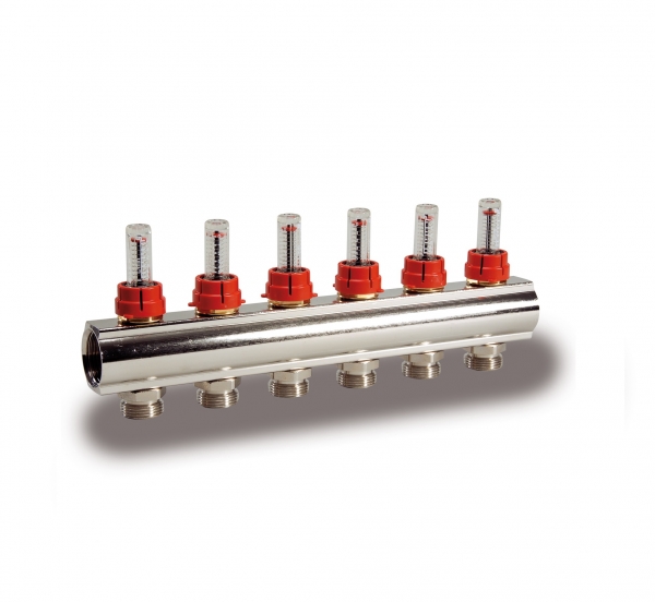
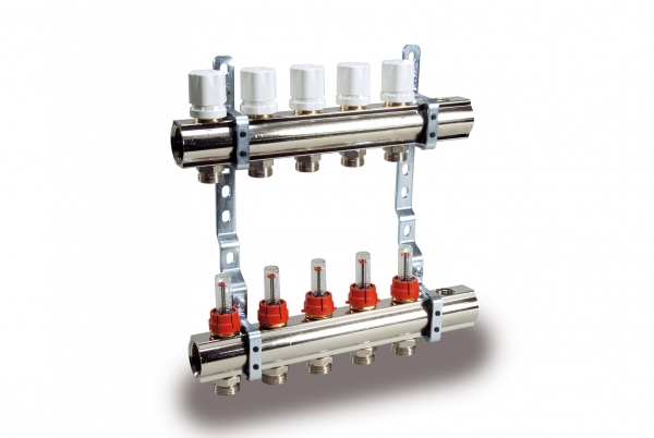
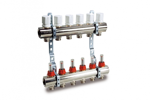
FLOW REGULATORS AND HOLDERS
With regulators and flow meters TM 4012, adjusting and balancing manifolds allow for an immediate verification of the system’s balance by reading the flow rate. This adjustment can be locked through a block cap. The glass and the measuring spring can be disassembled for maintenance and cleaned while the system is operating. This kind of manifold must be installed on the inlet.

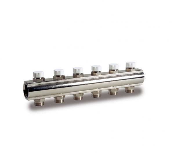
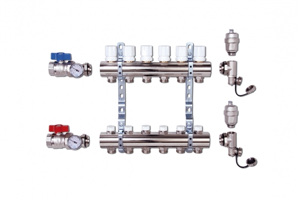
LOCKSHIELD VALVE
Adjusting and balancing manifolds (lockshield type) feature a double micrometric adjustment with memory of position in case of temporary shutdowns and can be mounted both on inlets and outlets of the system.

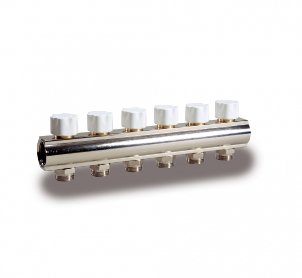
CONVERTIBLE HEADWORK
The tightening device on the stem of the manifolds with built-in valves for thermoelectric adjustment can be inspected and replaced while the system is operating. The control stem is in AISI 316 stainless steel and its tightness is ensured by two peroxide cured EPDM o-rings.
CD 474
Size
G 1” x G 3/4 EK
No. way
10, 11, 12, 2, 3, 4, 5, 6, 7, 8, 9

CD 1474
Size
G 1” x (W24x19)
No. way
10, 11, 12, 2, 3, 4, 5, 6, 7, 8, 9
CD 448
Size
G 1” x G 3/4 EK
No. way
10, 11, 12, 2, 3, 4, 5, 6, 7, 8, 9

CD 449
Size
G 1” x (W24x19)
No. way
10, 11, 12, 2, 3, 4, 5, 6, 7, 8, 9
CD 1446
Size
G 1” x G 3/4 EK
No. way
10, 11, 12, 2, 3, 4, 5, 6, 7, 8, 9

CD 1466
Size
G 1” x (W24x19)
No. way
10, 11, 12, 2, 3, 4, 5, 6, 7, 8, 9
CD 473M
Size
G 1”1/4 x G 3/4 EK
Finish
Nickel plating

CD 478M
Size
G 1”1/4 x (W24x19)
Finish
Nickel plating
CD 468M
Size
G 1” x G 3/4 EK
Finish
Nickel plating

CD 465M
Size
G 1” x (W24x19)
Finish
Nickel plating

CD 1877
Foro di scarico
Yes
Size
G 1”1/4 x G 3/4 EK

CD 1879
Foro di scarico
Yes
Size
G 1”1/4 x (W24x19)

CD 477
Foro di scarico
Yes
Size
G 1” x G 3/4 EK
CD 479
Foro di scarico
Yes
Size
G 1” x (W24x19)

CD 1873
Size
G 1”1/4 x G 3/4 EK
Finish
Nickel plating, Yellow
CD 1878
Size
G 1”1/4 x (W24x19)
Finish
Nickel plating, Yellow