ASSEMBLY INSTRUCTIONS
Luxor’s flexible hoses are produced for water adduction and distribution. The use of other liquid elements or chemical solutions is not guaranteed if not clearly agreed with the Technical Office.
Always carry out system test after the installation of the flexible hoses to check leakages or functional products defects.
Test the correct grounding of the electrical appliances (air conditioning systems, whirlpools, etc.) where hoses are connected. Any possible electrical dispersion could favor corrosive actions.
For installations in rooms with high humidity, where there is condensation, it is necessary to use flexible hoses with braiding and ferrules in stainless steel.
Design the system using hoses of adequate length and fittings to minimise hose twists and ten- sions (always check the product datasheets).
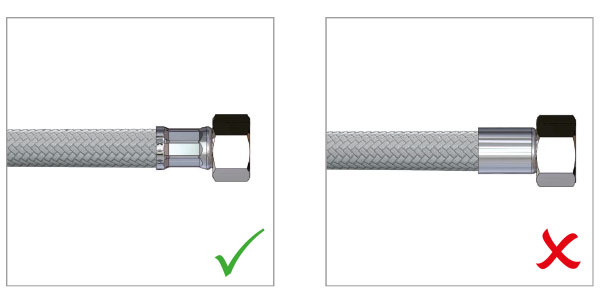
Always check that ferrules are pressed correctly and there are no braiding threads coming out. In case of doubts do not install the flexible hose.
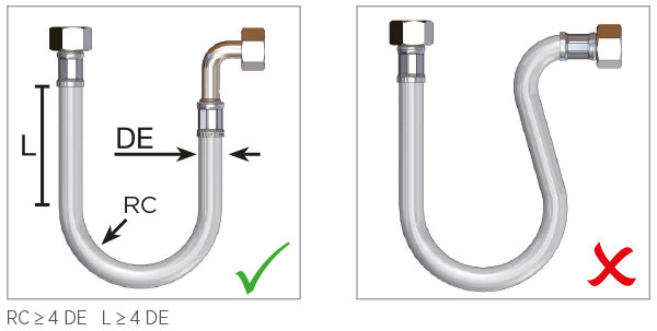
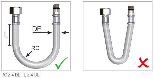
The hoses must maintain a straight section at the connections equal to 4 times the external diameter of the hose (DN6 = Ø 10 mm -> straight section 40 mm). The bending radius must not be less than 4 times the external diameter of the hose (DN6 = Ø 10 mm -> bending radius 40 mm).
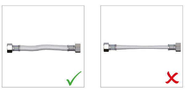
Do not install flexible hoses under twisting or tension conditions.
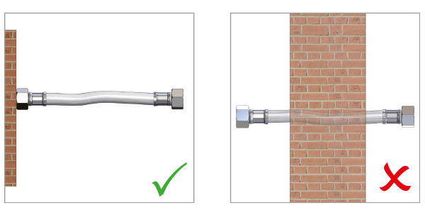
It must be possible to inspect the hoses. Do not install inside walls or in tunnels that cannot be inspected. Do not cover with insulating material (except for hoses with stainless steel braid and stainless steel ferrules.
Use only tools suitable for the type of product. The tools must only be used in the presence of a hexagonal nut. Any other configuration (cylindrical fitting, knurled ring nut, …) must be closed by hand (closing force not exceeding 3 Nm).
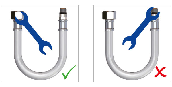
Do not use any tools on the ferrules. A force applied to this ferrule often causes it to become damaged with consequent breakage of the hose.
Never assemble two or more hoses in series. If necessary, choose a longer length.
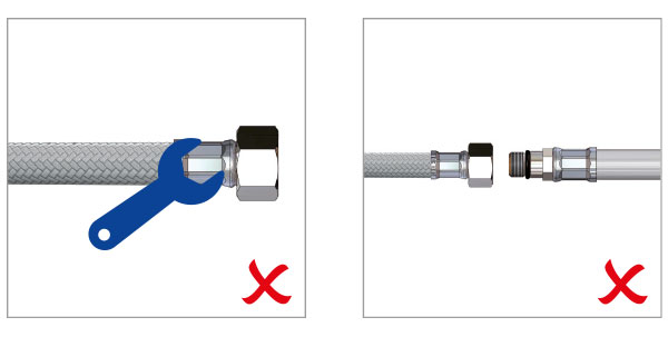
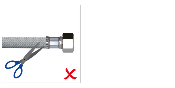
Avoid striking the hose with sharp or pointed objects to avoid damaging the external braid.
NORMAL END CONNECTION FITTINGS
- For a correct assembly please keep to the follow below instructions:
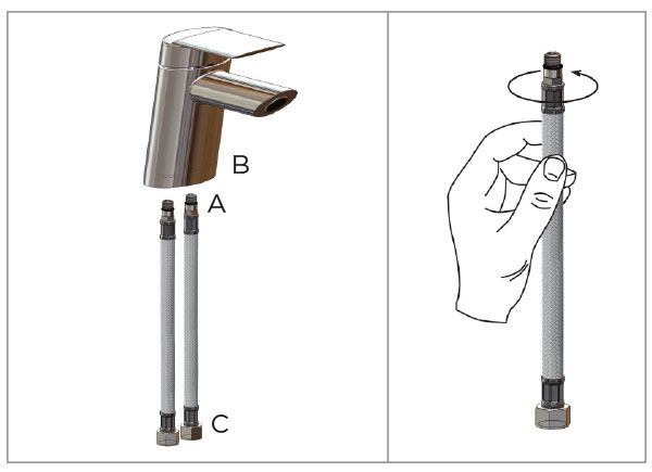
- check the threading of the fitting (A) of the flexible hose which must be corresponding to the one of the faucet’s body (B);
- check that the gasket is regularly placed on the female fitting (C);
- do not use hemp and/or Teflon on the thread (A) of the fitting.
Attention! Clamps from 2 to 3 Nm.
The male with o-ring seat are specially studied to guarantee the tightness betweeen the fitting and the body of the faucet.
It is not necessary to tighten with a key, the strength of the hand is enough.
COMPRESSION FITTINGS
For a correct assembly please keep to the following instructions:
- check that the cartridge (2) is correctly installed as per scheme since if this is upside down it causes tightening problems;
- the fightening fittings must be connected to pipes with a wall tickness not less than 0,75 mm. The compression fittings RCG, RCC and RCB must be tightened with a clamping couple in a range 25 nad 30 Nm.

MAINTENANCE INSTRUCTIONS
- Periodically monitor the state of the hoses.
In case of oxidation or evident state of wear, replace. - Avoid direct or indirect exposure to corrosive substances, including substances used for cleaning (bleach and similar substances).
- For cleaning only use damp (not wet) cloths without the aid of cleaning substances.
- Avoid striking the hose with sharp or pointed objects to avoid breaking the external braid (including boxes and containers made of metal, wood or other materials).
- In the case of systems in periodically uninhabited places (for example holiday homes or in places with particularly harsh climatic conditions) always check closure of the system and, in any case, avoid leaving the system pressurised.
LENGTH INSTRUCTIONS
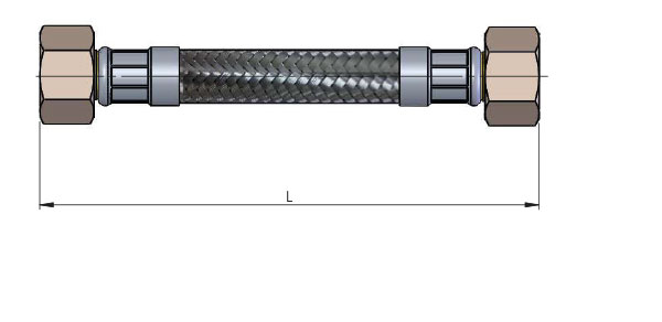
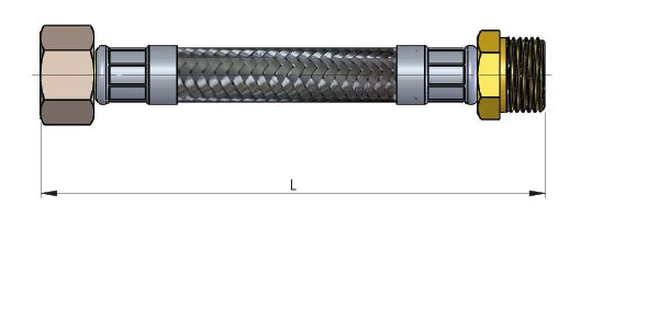
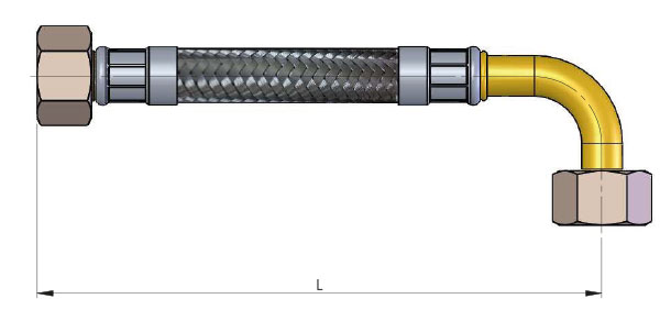
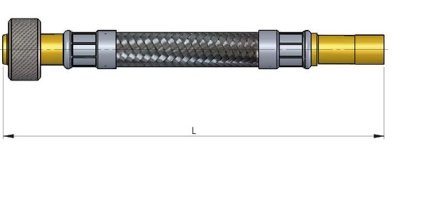
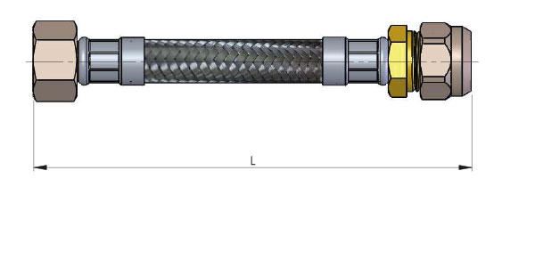
All hose assemblies shall be manufactured in lengths L measured as shown in Figure from a minimum of 90 mm to a maximum of 2000 mm, in compliance with standard EN 13618.
The actual length compared with the length L declared by the supplier shall be within the following permissible tolerances, in compliance with standard EN 13618:
L ≤ 400 mm: +10 mm / 0
400 mm < L ≤ 1000 mm: +20 mm / 0
1000 mm < L ≤ 2000 mm: +30 mm / 0


